Hello, I want to generate switching signals for a quasi z source inverter using the svpwm method. I can generate the traditional svpwm method, but I couldn't add shoot through time on it. I have researched on MathWorks and found that the code, but I don't fully understand the code. Although I understand what it does in general, I can't adapt it to the format used in my switching time table. I would be very grateful if someone help me on understanding how this code works. I have been trying to find a solution for 2 weeks.
My main problem is the second code; what sw_array and time_int do, why sw_array has 13 columns but there is only 12 it values. Also an example for sw_array") ,:,1) = [0 1 1 1 1 1 1 1 1 1 1 1 0; what is mathematical representation.
,:,1) = [0 1 1 1 1 1 1 1 1 1 1 1 0; what is mathematical representation.
function [t1,t2,t0,int1,int2,int3,int4,int5,...
int6,int7,int8,int9,int10,int11,int12] ...
= fcn(M,angle,Sector,D,Ts)
a = M;
n = Sector;
t1 = aTssin(npi/3 - angle);
t2 = aTs*sin(angle - ((n-1)pi/3));
t0 = Ts - t1 - t2;
tsh = DTs;
switch Sector
case 1
int1 = t0/4 - tsh/4;
int2 = int1 + tsh/6;
int3 = int2 + t1/2;
int4 = int3 + tsh/6;
int5 = int4 + t2/2;
int6 = int5 + tsh/6;
int7 = int6 + t0/2 - tsh/2;
int8 = int7 + tsh/6;
int9 = int8 + t2/2;
int10 = int9 + tsh/6;
int11 = int10 + t1/2;
int12 = int11 + tsh/6;
case 2
int1 = t0/4 - tsh/4;
int2 = int1 + tsh/6;
int3 = int2 + t2/2;
int4 = int3 + tsh/6;
int5 = int4 + t1/2;
int6 = int5 + tsh/6;
int7 = int6 + t0/2 - tsh/2;
int8 = int7 + tsh/6;
int9 = int8 + t1/2;
int10 = int9 + tsh/6;
int11 = int10 + t2/2;
int12 = int11 + tsh/6;
case 3
int1 = t0/4 - tsh/4;
int2 = int1 + tsh/6;
int3 = int2 + t1/2;
int4 = int3 + tsh/6;
int5 = int4 + t2/2;
int6 = int5 + tsh/6;
int7 = int6 + t0/2 - tsh/2;
int8 = int7 + tsh/6;
int9 = int8 + t2/2;
int10 = int9 + tsh/6;
int11 = int10 + t1/2;
int12 = int11 + tsh/6;
case 4
int1 = t0/4 - tsh/4;
int2 = int1 + tsh/6;
int3 = int2 + t2/2;
int4 = int3 + tsh/6;
int5 = int4 + t1/2;
int6 = int5 + tsh/6;
int7 = int6 + t0/2 - tsh/2;
int8 = int7 + tsh/6;
int9 = int8 + t1/2;
int10 = int9 + tsh/6;
int11 = int10 + t2/2;
int12 = int11 + tsh/6;
case 5
int1 = t0/4 - tsh/4;
int2 = int1 + tsh/6;
int3 = int2 + t1/2;
int4 = int3 + tsh/6;
int5 = int4 + t2/2;
int6 = int5 + tsh/6;
int7 = int6 + t0/2 - tsh/2;
int8 = int7 + tsh/6;
int9 = int8 + t2/2;
int10 = int9 + tsh/6;
int11 = int10 + t1/2;
int12 = int11 + tsh/6;
otherwise
int1 = t0/4 - tsh/4;
int2 = int1 + tsh/6;
int3 = int2 + t2/2;
int4 = int3 + tsh/6;
int5 = int4 + t1/2;
int6 = int5 + tsh/6;
int7 = int6 + t0/2 - tsh/2;
int8 = int7 + tsh/6;
int9 = int8 + t1/2;
int10 = int9 + tsh/6;
int11 = int10 + t2/2;
int12 = int11 + tsh/6;
end
function [Time_int,S1,S2,S3,S4,S5,S6] = ...
fcn(int1,int2,int3,int4,int5,int6,int7,int8,int9,int10,int11,...
int12,ref,Sector)
Time_int = 1 + (ref>=int1) + (ref>=int2) + (ref>=int3) + (ref>=int4) ...
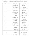
%% format of the array sw_array(x,y,z)
sw_array = zeros(6,13,6); %initialize the switching table
% x=[LegA LegB LegC] % y=[Timeint1 timeint2 ..] % z=[sector1 sector2 ..]
sw_array,:,1) = [0 1 1 1 1 1 1 1 1 1 1 1 0; ...
1 1 0 1 0 1 0 1 0 1 0 1 1; ...
0 1 0 1 1 1 1 1 1 1 0 1 0; ...
1 1 1 1 0 1 0 1 0 1 1 1 1; ...
0 1 0 1 0 1 1 1 0 1 0 1 0; ...
1 1 1 1 1 1 0 1 1 1 1 1 1];
sw_array,:,2) = [0 1 0 1 1 1 1 1 1 1 0 1 0; ...
1 1 1 1 0 1 0 1 0 1 1 1 0; ...
0 1 1 1 1 1 1 1 1 1 1 1 0; ...
1 1 0 1 0 1 0 1 0 1 0 1 1; ...
0 1 0 1 0 1 1 1 0 1 0 1 0; ...
1 1 1 1 1 1 0 1 1 1 1 1 1];
sw_array,:,3) = [0 1 0 1 0 1 1 1 0 1 0 1 0; ...
1 1 1 1 1 1 0 1 1 1 1 1 1; ...
0 1 1 1 1 1 1 1 1 1 1 1 0; ...
1 1 0 1 0 1 0 1 0 1 0 1 1; ...
0 1 0 1 1 1 1 1 1 1 0 1 0; ...
1 1 1 1 0 1 0 1 0 1 1 1 1];
sw_array,:,4) = [0 1 0 1 0 1 1 1 0 1 0 1 0; ...
1 1 1 1 1 1 0 1 1 1 1 1 1; ...
0 1 0 1 1 1 1 1 1 1 0 1 0; ...
1 1 1 1 0 1 0 1 0 1 1 1 1; ...
0 1 1 1 1 1 1 1 1 1 1 1 0; ...
1 1 0 1 0 1 0 1 0 1 0 1 1];
sw_array,:,5) = [0 1 0 1 1 1 1 1 1 1 0 1 0; ...
1 1 1 1 0 1 0 1 0 1 1 1 1; ...
0 1 0 1 0 1 1 1 0 1 0 1 0; ...
1 1 1 1 1 1 0 1 1 1 1 1 1; ...
0 1 1 1 1 1 1 1 1 1 1 1 0; ...
1 1 0 1 0 1 0 1 0 1 0 1 1];
sw_array,:,6) = [0 1 1 1 1 1 1 1 1 1 1 1 0; ...
1 1 0 1 0 1 0 1 0 1 0 1 1; ...
0 1 0 1 0 1 1 1 0 1 0 1 0; ...
1 1 1 1 1 1 0 1 1 1 1 1 1; ...
0 1 0 1 1 1 1 1 1 1 0 1 0; ...
1 1 1 1 0 1 0 1 0 1 1 1 1];
S1 = sw_array(1,Time_int,Sector);
S2 = sw_array(2,Time_int,Sector);
S3 = sw_array(3,Time_int,Sector);
S4 = sw_array(4,Time_int,Sector);
S5 = sw_array(5,Time_int,Sector);
S6 = sw_array(6,Time_int,Sector);
My main problem is the second code; what sw_array and time_int do, why sw_array has 13 columns but there is only 12 it values. Also an example for sw_array
,:,1) = [0 1 1 1 1 1 1 1 1 1 1 1 0; what is mathematical representation.function [t1,t2,t0,int1,int2,int3,int4,int5,...
int6,int7,int8,int9,int10,int11,int12] ...
= fcn(M,angle,Sector,D,Ts)
a = M;
n = Sector;
t1 = aTssin(npi/3 - angle);
t2 = aTs*sin(angle - ((n-1)pi/3));
t0 = Ts - t1 - t2;
tsh = DTs;
switch Sector
case 1
int1 = t0/4 - tsh/4;
int2 = int1 + tsh/6;
int3 = int2 + t1/2;
int4 = int3 + tsh/6;
int5 = int4 + t2/2;
int6 = int5 + tsh/6;
int7 = int6 + t0/2 - tsh/2;
int8 = int7 + tsh/6;
int9 = int8 + t2/2;
int10 = int9 + tsh/6;
int11 = int10 + t1/2;
int12 = int11 + tsh/6;
case 2
int1 = t0/4 - tsh/4;
int2 = int1 + tsh/6;
int3 = int2 + t2/2;
int4 = int3 + tsh/6;
int5 = int4 + t1/2;
int6 = int5 + tsh/6;
int7 = int6 + t0/2 - tsh/2;
int8 = int7 + tsh/6;
int9 = int8 + t1/2;
int10 = int9 + tsh/6;
int11 = int10 + t2/2;
int12 = int11 + tsh/6;
case 3
int1 = t0/4 - tsh/4;
int2 = int1 + tsh/6;
int3 = int2 + t1/2;
int4 = int3 + tsh/6;
int5 = int4 + t2/2;
int6 = int5 + tsh/6;
int7 = int6 + t0/2 - tsh/2;
int8 = int7 + tsh/6;
int9 = int8 + t2/2;
int10 = int9 + tsh/6;
int11 = int10 + t1/2;
int12 = int11 + tsh/6;
case 4
int1 = t0/4 - tsh/4;
int2 = int1 + tsh/6;
int3 = int2 + t2/2;
int4 = int3 + tsh/6;
int5 = int4 + t1/2;
int6 = int5 + tsh/6;
int7 = int6 + t0/2 - tsh/2;
int8 = int7 + tsh/6;
int9 = int8 + t1/2;
int10 = int9 + tsh/6;
int11 = int10 + t2/2;
int12 = int11 + tsh/6;
case 5
int1 = t0/4 - tsh/4;
int2 = int1 + tsh/6;
int3 = int2 + t1/2;
int4 = int3 + tsh/6;
int5 = int4 + t2/2;
int6 = int5 + tsh/6;
int7 = int6 + t0/2 - tsh/2;
int8 = int7 + tsh/6;
int9 = int8 + t2/2;
int10 = int9 + tsh/6;
int11 = int10 + t1/2;
int12 = int11 + tsh/6;
otherwise
int1 = t0/4 - tsh/4;
int2 = int1 + tsh/6;
int3 = int2 + t2/2;
int4 = int3 + tsh/6;
int5 = int4 + t1/2;
int6 = int5 + tsh/6;
int7 = int6 + t0/2 - tsh/2;
int8 = int7 + tsh/6;
int9 = int8 + t1/2;
int10 = int9 + tsh/6;
int11 = int10 + t2/2;
int12 = int11 + tsh/6;
end
function [Time_int,S1,S2,S3,S4,S5,S6] = ...
fcn(int1,int2,int3,int4,int5,int6,int7,int8,int9,int10,int11,...
int12,ref,Sector)
Time_int = 1 + (ref>=int1) + (ref>=int2) + (ref>=int3) + (ref>=int4) ...
- (ref >= int5) + (ref >= int6) + (ref >= int7) + (ref >= int8) ...
- (ref >= int9) + (ref >= int10) + (ref >= int11) + (ref >= int12);
%% format of the array sw_array(x,y,z)
sw_array = zeros(6,13,6); %initialize the switching table
% x=[LegA LegB LegC] % y=[Timeint1 timeint2 ..] % z=[sector1 sector2 ..]
sw_array
,:,1) = [0 1 1 1 1 1 1 1 1 1 1 1 0; ...1 1 0 1 0 1 0 1 0 1 0 1 1; ...
0 1 0 1 1 1 1 1 1 1 0 1 0; ...
1 1 1 1 0 1 0 1 0 1 1 1 1; ...
0 1 0 1 0 1 1 1 0 1 0 1 0; ...
1 1 1 1 1 1 0 1 1 1 1 1 1];
sw_array
,:,2) = [0 1 0 1 1 1 1 1 1 1 0 1 0; ...1 1 1 1 0 1 0 1 0 1 1 1 0; ...
0 1 1 1 1 1 1 1 1 1 1 1 0; ...
1 1 0 1 0 1 0 1 0 1 0 1 1; ...
0 1 0 1 0 1 1 1 0 1 0 1 0; ...
1 1 1 1 1 1 0 1 1 1 1 1 1];
sw_array
,:,3) = [0 1 0 1 0 1 1 1 0 1 0 1 0; ...1 1 1 1 1 1 0 1 1 1 1 1 1; ...
0 1 1 1 1 1 1 1 1 1 1 1 0; ...
1 1 0 1 0 1 0 1 0 1 0 1 1; ...
0 1 0 1 1 1 1 1 1 1 0 1 0; ...
1 1 1 1 0 1 0 1 0 1 1 1 1];
sw_array
,:,4) = [0 1 0 1 0 1 1 1 0 1 0 1 0; ...1 1 1 1 1 1 0 1 1 1 1 1 1; ...
0 1 0 1 1 1 1 1 1 1 0 1 0; ...
1 1 1 1 0 1 0 1 0 1 1 1 1; ...
0 1 1 1 1 1 1 1 1 1 1 1 0; ...
1 1 0 1 0 1 0 1 0 1 0 1 1];
sw_array
,:,5) = [0 1 0 1 1 1 1 1 1 1 0 1 0; ...1 1 1 1 0 1 0 1 0 1 1 1 1; ...
0 1 0 1 0 1 1 1 0 1 0 1 0; ...
1 1 1 1 1 1 0 1 1 1 1 1 1; ...
0 1 1 1 1 1 1 1 1 1 1 1 0; ...
1 1 0 1 0 1 0 1 0 1 0 1 1];
sw_array
,:,6) = [0 1 1 1 1 1 1 1 1 1 1 1 0; ...1 1 0 1 0 1 0 1 0 1 0 1 1; ...
0 1 0 1 0 1 1 1 0 1 0 1 0; ...
1 1 1 1 1 1 0 1 1 1 1 1 1; ...
0 1 0 1 1 1 1 1 1 1 0 1 0; ...
1 1 1 1 0 1 0 1 0 1 1 1 1];
S1 = sw_array(1,Time_int,Sector);
S2 = sw_array(2,Time_int,Sector);
S3 = sw_array(3,Time_int,Sector);
S4 = sw_array(4,Time_int,Sector);
S5 = sw_array(5,Time_int,Sector);
S6 = sw_array(6,Time_int,Sector);